UnintegratedCircuit
Part 7 - The Software
The IDE and Prerequisites
Since this project uses a PIC microcontroller without any fancy serial upload bootloaders like the Arduino platform offers, the programming is a little more involved than simply pluggin in a USB cable and hitting upload. There are some things that will be required, these are listed below:
-
The MPLAB X IDE, at least version 5.0 or newer to be safe;
-
Plus the XC8 C compiler;
-
-
A PICKIT 3 or PICKIT 4 or MPLAB Snap;
-
If one chooses not to include some header pins on the PCB, and wishes to program SMD packaged microcontrollers, a suitable adapter will also be required.
Some things of note:
-
There may or may not be an option to install a set of libraries or similar when installing the MPLAB X IDE, if there is an option to include these for 8-bit devices, tick it (I will confirm this on my next MPLAB X re-install).
-
The MPLAB X IDE and XC8 C compiler are both available for free; however, the links to the free downloads are not always the easiest to find on the page.
-
The MPLAB X IDE and XC8 C compiler can be installed anywhere on a system with just about any file structure (as far as I know), my current install is on a portable SSD drive in order for me to use it on university systems if needed; however, one will need to set file paths to the compiler manually which is a major pain. Default install locations will 'just work' 'out the box'.
-
The PICKIT3, while no longer offered officially by Microchip, is still available for dirt cheap (£10 or less as of January 2021) off ebay along with all the necessary cables. I own a knockoff one and it has worked faultlessly for me for nearly 4 years now and is probably cheaper than either of the other options listed.
-
The programming adapters are available for almost every SMD package on places like Amazon and eBay; however, some can be quite expensive (generally the more 'common' the package, the cheaper the socket, e.g. SOIC-8 adapter is very cheap).
-
Not all SMD packages are created equal, the more intricate packages like the QFN-16 and similar can have different sizes/pin pitches which might not be identical across every part, check carefully to make sure you buy an adapter that matches the exact component.
The Configuration Bits
The first thing to do when writing any program for a PIC microcontroller is to determine, at least roughly, what configuration bits are to be set/cleared (1/0 respectively). The configuration bits essentially define the core operating characteristics - as well as some of the power on defaults - of the microcontroller such as whether to allocate some program space for a bootloader, or whether to enable the watchdog timer, etc.
The easiest way to manage these is by clicking, on the top bar: "Window" -> "Target Memory Views" -> "Configuration Bits". The settings for this project are shown below in Figure 1.

Figure 1 should be fairly self-explanatory as the right-most column gives an explanation as to what each setting actually does; however, if any of the terms/acronyms used are not familiar, one can always Google or take a look at the datasheet where a more in-depth explanation should be available. As a general rule though, anything that is essential to the operation of the rest of the program has been enabled, and any additional options have been disabled - mostly because these options add complexity and this is not a project that is liable for anything important like data security or injury to the user.
As an example of this, in the second line, the internal oscillator clock frequency has been set to default to 1MHz at power on, but this comes with a catch: it actually runs the clock at 4MHz and divides this frequency by 4 to achieve the 1MHz that was requested. As a result, I have enabled the ability to change the clock frequency/clock divider ratio by choosing the correct setting on the 4th line (setting CSWEN to 'ON').
Enabling a function such as the WatchDog Timer (WDT) however, makes no sense. The WDT's job is to automatically reset the microcontroller if the code crashes. To make sure the WDT never times out, the CLRWDT instruction must be executed periodically (i.e. the microcontroller then 'knows' that it has not crashed), and this process just introduces an extra, and in this case unnecessary, consideration.
The Include Files
The next thing I do in my C programs is list all the 'include' files. These files essentially link the current program with other bits of (often very useful) code that has already been written by someone else. For example, one include file math.h links to a piece of code that allows one to find the square root of a number, something that's both useful and relatively complex/time-consuming to do yourself for every program that requires it.
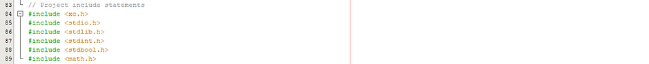
Figure 2 shows the include files required for this project. stdbool.h is particularly useful as it greatly eases the process of declaring boolean variables (values that could be either true or false). stdint.h allows one to explicitly declare whether a number if signed or unsigned, as well as its length in bits. xc.h is used by the XC8 compiler and (I believe) allows one to reference the various internal registers by name, making the code far more readable. stdio.h and stdlib.h may not actually have been used in this program; however, the compiler only includes the relevant code, so if they're not used then it has no impact on the final program. math.h was included so that the rand() and srand() functions could be used, both of which pertain to the generation of 'random' numbers.
The Oscillator Frequency Definition
Figure 3 shows the line that tells the compiler what frequency the device oscillator is running at. This allows it to generate the correct code in place of any delay() statements. There is plenty of information online about the various methods of creating a delay, quite a good one for PIC microcontrollers can be found here.
The oscillator frequency was 'defined' as 4MHz (4,000,000Hz) as seen on line 93 because, despite telling the microcontroller to power up with a 1MHz frequency, this is instantly changed to 4MHz by reducing the clock frequency divider.
Usage of Random Numbers
Random numbers feature heavily throughout this project, in an attempt to recreate a natural flickering flame effect and to maximise viewing interest. Figure 4 showcases the three different applications of the random numbers: Selecting a random Nixie cathode, creating a random delay between selecting cathodes, and generating a random bitstream to the 'output enable' pin of the shift register to create the flickering effect.
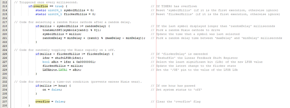
Line 219 shows how a random number has been used to select a Nixie cathode. By using the modulo function (the percent sign), the range of the random number can be constrained as follows: the modulo function returns the remainder after a division. In the case of line dividing by 8 as with line 219, the possible remainders are 1, 2, 3, 4, 5, 6, 7 & 0 (i.e. the number was a multiple of 8). This conveniently translates into all the possible indices of an array with length 8. symbols is a Look-Up Table (LUT) - essentially just an array where the elements are retrieved and used as values elsewhere - and it stores all the possible combinations of selecting exactly one cathode of the IN-19V Nixie tube.
Line 221 shows how the delay is implemented for the cathode selection. This is much the same as the method just described, except for a slight modification that allows one to set both a maximum and a minimum value for the random number. This prevents the animation from skipping through cathodes unnecessarily fast which would create a much more jarring effect, as opposed to the relaxing effect that was intended.
Finally, lines 226 & 227 show the third implementation of a random number: a Linear-Feedback Shift Register (LFSR). This LFSR effectively takes a string of bits, 24 in this case, and (after seeding with a starting value) scrambles it up and shifts the bits around. As the number of bits increases, the sequence lengths without repetition get ridiculously long. In this instance, the only part of this 24-bit string that gets used is the least significant bit. This bit is then 'extracted' by using a bitmask and saving the result as a boolean value (aBit). This boolean is then used to set the state of the 'output enable' line from the MCU to the shift register, hence causing the flickering effect by rapidly turning the selected cathode on and off.
Random Number Seeding
Due to the way that random numbers work (applying a complex algorithm to the current number each time the rand() function is called), if one fails to provide a unique starting value (all known as a seed) then every time the program is run, the same 'random' numbers will be used. To combat this, I used the PIC's built-in bandgap temperature indicator to generate truly random seed values for the random numbers.
A bandgap temperature sensor works by exploiting the energy difference between the valence and conduction bands of a semiconductor P-N junction (in this case involving the silicon die inside the IC). As an electron gains energy, it will 'jump up' to the conduction band, allowing it to move across the junction, thus allowing a current flow. In this case, the supply of energy is not just from an applied voltage, but also the temperature of the silicon die - as the temperature increases, so does the energy available to the electrons, and hence the current increases (and is then measured by the ADC).
Since the ambient temperature will almost always be different when the seeding routine (shown in Figure 5) is called, the temperature of the die will be different, and therefore so will the seeding value. Additionally, as the device operates, the die temperature will change, further adding to the variation of the seed value.
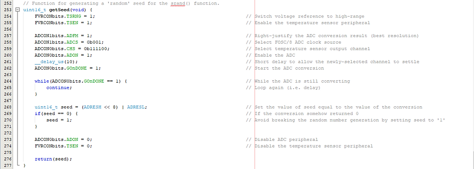
Figure 5 is fairly self-explanatory, especially with the comments. Essentially, it configures and enables the fixed-voltage reference & temperature sensor peripherals so as to give the greatest temperature sensitivity, takes an ADC reading of the temperature sensor, and then disables the peripherals, placing them back into a low-power state.
Interrupt Service Routine
A simple Interrupt Service Routine (ISR) was written to handle two things:
-
A timer that triggers every millisecond, so as to provide non-blocking delays for other bits of code (for example, the delays shown in figure 4).
-
Some code that latches data to the shift register outputs whenever data has finished being shifted out to it.
Figure 6 shows the actual ISR, although most of the setup of the registers is done elsewhere and, especially for ISRs, the setup is the most critical part for an efficient system - if the correct interrupts are configured, and if they are properly handled, it can considerably improve the program both in terms of speed and complexity.

The most important part of this ISR is clearing the interrupt flags (PIRxbits.xxx). If this is not done, then the MCU assumes a new interrupt has occurred and immediately goes back into the ISR. This makes it appear as if the MCU crashes, although, in reality, it is a classic case of the MCU doing as you instructed, not as you intended.
Power Button Handling
The final main aspect of this code was how to implement the power button. The only pin remaining on the PIC MCU was the reset pin (which could also be configured to act as a digital input). For some interesting reason, instead of using it as a digital input, I decided to maintain its function as the reset input. Figure 7 below, shows the first few lines of executed code after a reset.
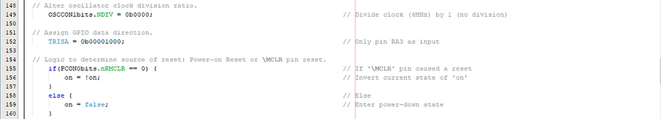
As can be seen, after the system clock divider has been altered (from 4 to 1), and after the inputs and outputs have been set correctly, the code determines what the cause of the reset was. The expected resets, considering that the watchdog timer and brown-out reset circuitry have been disabled, are:
-
Power-On Reset (POR)
-
Master CLeaR reset (MCLR)
From this code, since a POR is not an MCLR reset, the on variable will be set to false, the system will be configured as normal, and then will immediately enter sleep mode where everything is placed in standby. In the case of an MCLR reset, however (i.e. the user presses the power button), the system will reset and reconfigure as above, but the state of the on variable will simply invert (i.e. toggles the system between on and off).
Granted this is not the optimal way of implementing this, but it is a way to do so and, should you find yourself with a microcontroller that does not have the ability to configure the reset pin, this is likely a viable workaround.
Shift Register Interface
A quick point to mention is the interface between the MCU and the shift register. This is implemented using SPI via the Master Synchronous Serial Port (MSSP) peripheral. Once this peripheral has been correctly configured, the data can be shifted out to the 74HC595 shift register, and if interrupts are implemented, the data can be latched in immediately via the ISR (see Figure 6). This not only allows for faster data transfer rates versus setting the pin states manually but also removes a lot of overhead from the microcontroller, allowing for either more instructions to be executed or a slower system clock to be used (and hence lower power consumption).
The next, and final, part of this project will provide a very brief wrap-up as well as a photo and video of the finished project working.