UnintegratedCircuit
Part 1 - The IV-15 Tube
Vacuum Tube Basics
I am by no means an expert on vacuum tubes (I was born this side of the millennium after all); however, I have been doing a fair amount of reading on Vacuum Fluorescent Displays (VFDs) in general, especially the smaller, single-digit tubes offered as new old stock Russian imports on eBay and similar sites.
VFD displays have a fairly simple fundamental operation, consisting of three main parts:
-
A filament with a special coating;
-
A wire mesh control grid;
-
A phosphor-coated anode.
Starting with the filament, this is electrically identical to an ordinary lightbulb filament, that is, a component that runs hot under normal operating conditions and where the resistance increases with temperature. This means that upon initial application of power when the filament is cold and its resistance is low, there is a relatively large surge of current. This surge of current is the most common mode of failure in the common filament lightbulb. The coating mentioned is specifically designed to release electrons when heated, the heating in question comes from passing a current through the filament since power is dissipated as heat and power can be related to current and resistance by the equation below.
Moving onto the control grid, this presents itself as a wire mesh that would typically draw a few tens of milliamps for smaller displays. The grid acts to accelerate the electrons emitted by the filament towards the anode(s) so that the electrons have enough energy to cause the phosphor on the anode to fluoresce. Therefore by applying a voltage that is positive with respect to the filament to the grid, the electrons (with their negative charge) are attracted towards this positive potential - this is an example of actual electron flow as opposed to conventional current flow. Similarly, if you apply a voltage that is negative with respect to the filament, this will repel any emitted electrons and effectively turn off the entire display. This is comparable to a 'display enable' function that is common amongst many display driver chips, including those in the 7400 and 4000 logic series ICs.
Finally, the anodes of the display also have a positive voltage applied, to further attract the electrons, this also provides the individual illumination of segments on a seven-segment display tube - if a segment has a positive voltage applied to it, it will attract electrons to it, causing the phosphor to fluoresce; however, if a negative voltage is applied to it it will repel the electrons approaching it meaning that the phosphor cannot fluoresce hence keeping the segment extinguished.
Figure 1 shows the segments of an IV-11 VFD tube along with the clearly visible mesh of the grid. Figure 2 emphasises the VFD filament again in an IV-11 tube, there are two lengths of filament wire inside these tubes.


In the case of most VFDs, the grid and anodes can share the same positive voltage supply, typically being between about 12V and 24V for static (non-multiplexed) displaying and increasing up to about 50V for multiplexed applications. The IV-15 tube being used here though is not like a standard VFD, it's essentially a small triode but with a phosphor coating on the anode so that it can be used in indicator applications without requiring the even higher voltage a neon indicator would need.
Figure 3 below shows the IV-15 in its entirety, leads and all.

A Simple Test Circuit
Now for a quick test circuit, only a handful of basic calculations need to be made as these tubes are fairly forgiving. A quick look at the datasheet through the Google Translate app shows some specifications that need to be considered for this basic test circuit.
-
Anode maximum voltage: 50V
-
Filament voltage: 0.8V
-
Filament current: 42mA +/- 5mA
In addition to this, a general rule of thumb is to keep the grid voltage between 0V and 5V (when I've been testing at higher anode voltages, the grid voltage did not have a massive effect on the brightness past 5V, sure it had some, but not masses). With this in mind, I set about designing a quick and easy test circuit using only a 9V battery, the tube and a few common value resistors.
For starters, the maximum anode voltage rating will definitely not be exceeded using a 9V battery - in fact, this is barely enough to illuminate the tube.
Next, I set about biasing the grid to about 5V. This is most easily achieved using a potential divider formed of two resistors as according to the equation below.
By setting R1 equal to R2, VOUT will be equal to half of VS. In the case of the 9V battery (9V being the value of VS), VOUT will be equal to 4.5V which is close enough to the 5V recommended 'fully on' voltage of the control grid. R2 can also be swapped for a potentiometer as long as the potentiometer is equal in value to R1 (i.e. both 1kΩ or both 10kΩ) and this will allow the somewhat limited brightness to be adjusted. This is proven below.
Finally, the filament can be hooked up. The easiest way to do this is to put enough series resistance to run it directly from the 9V battery as well. The filament itself has a resistance ranging from about 5.6Ω when cold to about 17Ω when hot in my case. With this knowledge, and by applying Ohm's law, a rough value of series resistance can be calculated as follows:
Based upon this calculation, and the knowledge that the filament can tolerate a +/-5mA deviance, a resistance of 200Ω would be ideal. This can easily be made by placing two 100Ω resistors in series or it could be swapped out for a single 220Ω resistor. It should be noted that this resistor must be placed between positive and one end of the filament (as shown in the schematic in Figure 4) or else there will be no potential difference (and therefore no attraction of electrons) between the anode and the filament which would result in no glow.
In the final design I opted to place two 100Ω resistors in series between positive and one end of the filament, and then an extra 10Ω of resistance between the other end of the filament and ground. This raises the potential of the filament slightly above 0V which means that, when 0V is applied to the grid, the tube is guaranteed to be fully extinguished and there is no residual glow. All in all, the final schematic is as follows:

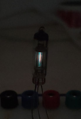
Figures 5 and 6 below show the tube in the test circuit with the grid voltage at 0V and 4.5V respectively. These images were taken in a dimly lit room (curtains closed but with light seeping in from underneath) and with the exposure locked to give a completely relative comparison. The photo does make the glow in figure 6 look far more impressive than with the naked eye; in reality, it has a dull glow that is much more green than the image would imply. This is only due to the low anode voltage, however.

With the tube now verified to be working, attention can now be turned to starting the main project: a nightlight that uses this tube to provide a relaxing cyan glow.